How to build an Intermediate Distribution Frame (IDF)
We like to think of an Intermediate Distribution Frame (IDF) as the arteries of a commercial space. Your IDF [0] is the central point on your building’s floor where all internet connectivity (i.e., fiber, coax cable) originates. It holds the telecom and network equipment needed to activate an internet connection and distribute it throughout the space.
Given its critical role in providing your internet & WiFi, it’s important to take the design and build of your IDF seriously, keeping in mind the load of the network, outages, future equipment planning, requirements of all vendors (e.g., WiFi, AV, security), and aesthetics.
Here’s what we’ll cover:
- Creating your IDF
- Sizing & designing a network rack
- Selecting equipment
- Delivering your ISP provider
- Connecting your network equipment
- Maintaining your IDF
Creating your IDF
If you’re moving into a new space, you’re best off planning your IDF build at least 90 days in advance to account for the installation of telecom cabling and equipment. If your space is currently under construction, planning your IDF build before electrical circuits and air ducts are installed helps ensure your IDF has sufficient power and ventilation.
Location
For most existing spaces, the location of your IDF will already be determined. If your space is under construction and you have the luxury of deciding where to place your IDF, choose a spot that’s easy to run cabling from your riser shaft [1] and is in the center of your space to make cable runs to access points shorter. The shorter your cable runs, the cheaper your installation and faster your data rates.
You’d be surprised by where some network equipment is placed. We’ve seen a rack of equipment directly underneath a water tank, IDFs with prewar lead insulated electrical wiring, and a server cabinet made of wood (not exactly good for ventilation).
Power
If you’re moving to an existing space, the power capacity of your IDF will already be set, and any changes will involve hiring an electrician to rewire the electrical circuits. If your space is under construction, determine your IDF’s power needs by summing the maximum watts drawn by your controller, switches, wireless access points, and ISP modems. If total watts drawn is over 3,600 (i.e., 120 volts * 30 amps), you’ll need a 220V outlet. In general, it’s safest to opt for a 220V outlet over a 110V outlet in case your power needs increase in the future.
Ventilation
To prevent your network equipment from overheating, you’ll want to make sure the temperature in your IDF is between 65 and 85 degrees Fahrenheit. You can do so by ensuring that your IDF has a supply and return from your ducted HVAC system or by installing a ductless HVAC system.
Sizing & designing a network rack
We recommend installing the following networking equipment in your IDF:
- Rack & Wire Manager: holds all of the equipment in the IDF to make it easy to work with.
- Uninterruptible Power Supply (UPS): backup power in the event of a power outage.
- ISP Modems: provides an internet connection to the outside world. If your primary and secondary internet service providers don’t need to supply a modem, they’ll terminate a coax or fiber connection directly into your controller.
- Controller: a server for your local network—manages wireless access points, processes data and acts as a firewall, among other things.
- Power over Ethernet (PoE) Switches: provides power and ethernet to wireless access points and ethernet cable runs [2].
- Patch Panels: organizes connections from wireless access points and ethernet drops to PoE switches.
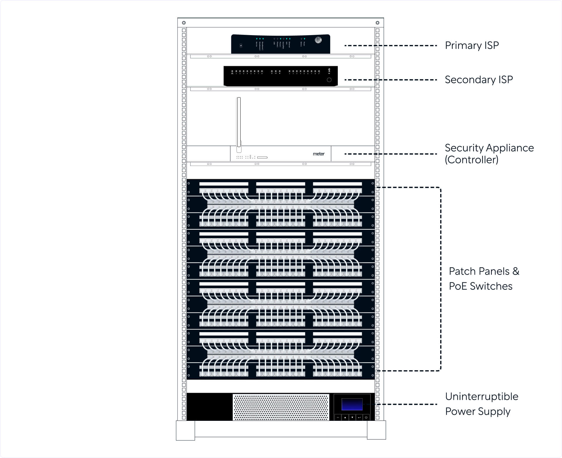
Below is a photo of a 45U [3] rack in an IDF responsible for providing connectivity to a 40,000 sq ft office. Let’s work backwards to learn how to get here.
Rack size
Your rack will need to be tall enough to hold all of the IDF equipment mentioned above. Rack size is measured in rack units (abbreviated as U), where each unit is 1.75 inches. The rack pictured above is ~6.5 feet tall (78.75 inches) since it’s a 45U rack. The size of your rack will determine whether it’ll be wall-mounted or standalone, with racks larger than 12U usually being standalone. A note on terminology: anything 12U or smaller may be referred to as a cabinet.
You’ll notice that there is quite a bit of space between some of the units in the photo above. This is intentional to make working with the equipment easier, as well as providing enough space for new equipment. With that said, there aren’t gaps between the PoE switches as doing so would disrupt a switch’s front-to-back cooling by letting air flow above and below them.
Rack elevation
We generally recommend you organize the rack as shown in the picture above with the ISPs coming in at the top followed by the controller, PoE switches interleaved with patch panels, and an uninterruptible power supply.
Doing so makes connecting to the controller—the brains of your network—easy. Similarly, interleaving PoE switches with patch panels makes running connections between them easier. The uninterruptible power supply is a heavy battery that’s best placed on the floor. We also advise labelling the units on the sides of the rack to indicate which equipment occupies each unit.

All of the equipment except your ISP connections (i.e., a rack, uninterruptible power supply, controller, PoE switches, and patch panels) can be installed on the same day.
Selecting equipment
Planning for port & power capacity
Running through the calculations below will help you determine both the type and number of switches, as well as the type of UPS you’ll need in your IDF.
Switch ports
You’ll want to make sure you have enough available ports to connect to the controller, each wireless access point, and other devices that require an ethernet cable (e.g., wired workstations, security cameras, AV equipment). Use the following calculation to determine the number of ports required:
Number of Ports = 1.2 * (N + M)
In the formula above, N is the number of wireless access points installed, and M is the number of other cable drops rounded to the nearest integer. The 1.2 multiple adds a 20% buffer, which helps to account for the port that connects to the controller and any ports that may be added later on.
Switch power
Different wireless access points draw different amounts of power, but in general, you can estimate that an access point draws a max of ~25W of power. To estimate the amount of switch power needed, apply this formula:
Power requirement of switch(es) = 1.2 * (25W * N)
In this calculation, N is the number of wireless access points installed, and again, a 20% buffer is added to ensure you have enough power while access points are at max power.
UPS power
If the power goes out in your space, you’ll need a backup power supply to keep the network live. Given the specifics of how each manufacturer designs their UPS (e.g., battery chemistry, wire gauges), we can’t recommend a generic formula for calculating power requirements. Rather, you should rely on the runtime graphs and data sheets that manufacturers provide, while discounting these results by 10-20% to be safe.
While a UPS is helpful during short power blips, don’t expect it to run your network during prolonged power outages. In general, aim to get a UPS that can keep your equipment powered on for at least 20 minutes. Any power outages that last longer than 20 minutes usually mean people have gone home.
Planning for redundancy
Making your system redundant protects it against single points of failure. The four areas where a hardware or power failure can bring down all, or part, of your network are: switches, the controller, ISP equipment, and electrical power.
Switch redundancy
The failure of one switch shouldn’t kill power and ethernet to a cluster of access points in the same region. You can protect against this by connecting adjacent ports on a patch panel, which for the most part represent access points that are near one another, to different switches. For instance, if you’re building an IDF with four, 48-port switches, this is what the connections from the ports on the first patch panel would resemble:

Notice that wireless access points numbered one through four are all connected to a different switch. As shown above, we recommend you don’t connect all of a switch’s ports to wireless access points. You should intentionally connect only 30% to 50% of a switch’s ports to access points to provide room for current and future ethernet drops, while not overloading the switch’s power capacity.
Controller redundancy
Similar to all hardware, your controller can malfunction. Because this is a critical component of the entire system, you should have an extra provisioned controller in your IDF that’s ready to replace the current one at a moment's notice.
ISP redundancy
If your internet service provider experiences an outage, you’ll want to have a secondary ISP connection that your controller can fallback on. To keep your network live if both ISPs are down, plug an LTE SIM card into your controller. This will run the network on LTE during the ISP outages, but keep in mind, LTE offers a weaker, more costly connection.
Power redundancy
Connect all of your network equipment to an uninterruptible power supply to keep your network running during a power outage. We discussed above how to size your UPS.
Delivering your internet service providers
After sourcing a primary and secondary ISP connection, you’ll have to project manage the installation of these ISP connections. If an ISP doesn’t already have physical cabling in your building, they’ll have to run a connection from the street to your building’s Main Point of Entry (MPOE [4]); and if they’re not in the street, they’ll have to dig a trench in the street to lay their connection.
Once an ISP’s cabling crosses your building’s MPOE, coordinate with your building’s riser manager to run the cabling from the MPOE to your IDF. The ISP will then install a modem on your rack and terminate a coax or fiber connection into this modem. From here, you’ll have to connect the primary and secondary ISPs’ modems to the WAN ports on your controller. If the ISP doesn’t require installing a modem, they’ll terminate their connection directly into your controller.
This is the most variable timeline in the process. If your preferred ISPs are already available in your building, setup may only take a few weeks. If not, you’ll need to coordinate with the ISP and your building’s riser management to establish a connection, which may take a few months. On the extreme end, we’ve seen this take 6+ months.
As an interim solution, you can connect an LTE hotspot to your controller. We recommend a mobile router with a Twilio SIM card to make managing data limits and spending easy. As mentioned above, if your controller supports LTE, you can simply put a SIM card in your controller.
Connecting your network equipment
After installing wireless access points and ethernet drops throughout your space, ethernet cables are run from these access points and drops to the IDF. Once in the IDF, we recommend they be terminated in back of a patch panel. Each port on your patch panel should be labelled with the type of connection coming in (e.g., WAP-05 to indicate the fifth wireless access point). We also recommend color-coding them to delineate between connection types (e.g., green for wireless access points, yellow for ethernet drops, purple for security and audio visual equipment). You can terminate cables directly into a PoE switch instead of a patch panel, but doing so makes it tough to organize a mass of cables.
Ethernet cables then run from ports on the front of a patch panel to the associated port on a switch. Connect a switch to your controller by running an ethernet cable from the first port on the switch to a LAN port on your controller. These switches, in aggregate, represent the connections that form your local network. To ensure your network can stay online during a temporary power outage, connect the switches and controller to an uninterruptible power supply, which should be connected to a power outlet.
Maintaining your IDF
With your IDF now built, you’ll need to consider how to keep it secure and functional over the long-term.
Security
Your IDF holds all of your essential telecom and network equipment. If someone were to break in, they could hack into your corporate network, potentially giving them access to the applications your employees use and the ability to crash your network. To optimize security, here are a few best practices:
- Keep your IDF locked and document who has key access.
- If you need 12Us or less to hold your network equipment, opt for a cabinet with a door and lock.
- Install a security camera outside your IDF to monitor activity and disincentivize unauthorized personnel from entering.
- Maintain a log of when and why the IDF was accessed, and verify the identity and intent of any vendors who require access.
- Avoid using your IDF for storage to lower the frequency of having to grant IDF access.
Avoiding outages
Avoiding outages is a function of maintaining the equipment that is connected to or contained within the IDF. For example, you’ll want to make sure the software running on your controller and wireless access points is regularly updated, and you should plan to upgrade your equipment and cabling approximately every 5 years. And since even a well-maintained system will face outages, you’ll want to hire a trustworthy IT & Networking vendor who can quickly respond to any unexpected events, especially during non-business hours.
After building your IDF and turning on an ISP or LTE connection, your network will be live. Be sure to test the network for speed and coverage and tune the wireless access points as you see fit.